

PDA8232-N
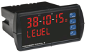
PD6001 ProVu Analog Input Feet & Inches Meter
Precision Digital
Request a Quote
Call for Pricing & Availablility
PDA1004
PD6001 ProVu Analog Input Feet & Inches Meter
Precision Digital
Request a Quote
Call for Pricing & Availablility
PDA1232
PD6001 ProVu Analog Input Feet & Inches Meter
Precision Digital
Request a Quote
Call for Pricing & Availablility
PDA1044
PD6001 ProVu Analog Input Feet & Inches Meter
Precision Digital
Request a Quote
Call for Pricing & Availablility
PDA1002
PD6001 ProVu Analog Input Feet & Inches Meter
Precision Digital
Request a Quote
Call for Pricing & Availablility
PDA3900-12-N
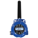
PDW30 Point-to-Point Wireless Bridge
Precision Digital
Request a Quote
Call for Pricing & Availablility
PDA30-RNA
PDW30 Point-to-Point Wireless Bridge
Precision Digital
Request a Quote
Call for Pricing & Availablility
PDA10
PDW30 Point-to-Point Wireless Bridge
Precision Digital
Request a Quote
Call for Pricing & Availablility